Broken screen? dont worry, we have a full step by step guide to get you back up and running!
Motorola Edge 50 repair

Screen Replacement - Edge 50
1 HOUR
VIDEO / PHOTO GUIDE
Parts Used
Tools & Consumables Required
Technician notes:
This repair can be time-consuming, so patience is key, especially when dealing with adhesives—particularly during battery removal. Avoid using metal tools or pulling the battery out forcefully. If possible, it is also recommended to fully discharge the battery before starting the repair.
This repair can be time-consuming, so patience is key, especially when dealing with adhesives—particularly during battery removal. Avoid using metal tools or pulling the battery out forcefully. If possible, it is also recommended to fully discharge the battery before starting the repair.
- SIM Tray Removal


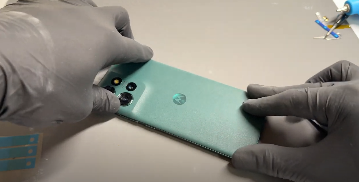
Prepare your work area - once ready, remove your SIM card tray using the SIM Eject Tool.
- Battery Cover Removal
Gently heat the phone’s back cover using a hairdryer on medium or a heat gun on low until it feels warm to the touch. This helps soften the adhesive for easier removal.
Using a metal pry tool or a handled blade, carefully create a small gap between the back cover and the frame. Once a gap is established, insert a plastic card, playing card, or a thick piece of paper. Slowly slide it around the edges to loosen the adhesive seal, taking care not to damage internal components.
Reapply heat as needed to further soften the adhesive. Once the seal is fully loosened, carefully lift the back cover, using the card tool to separate any remaining adhesive. Take your time and proceed gently.
Once separated, carefully remove all old adhesive from both the phone’s frame and the back cover (unless it's being replaced). This step can be time-consuming, so patience is key.
If available, apply a small amount of isopropyl alcohol (IPA) or acetone (such as nail polish remover) to a cotton swab and gently dab it onto the adhesive to help break it down. This will make removal easier and ensure a clean surface for reapplication.
Alternatively, use a plastic or nylon tool to gently scrape off the adhesive without damaging the phone’s frame or components. Be thorough in this step to ensure a secure fit when reattaching the cover.
- Middle Frame & Sub-Board Removal
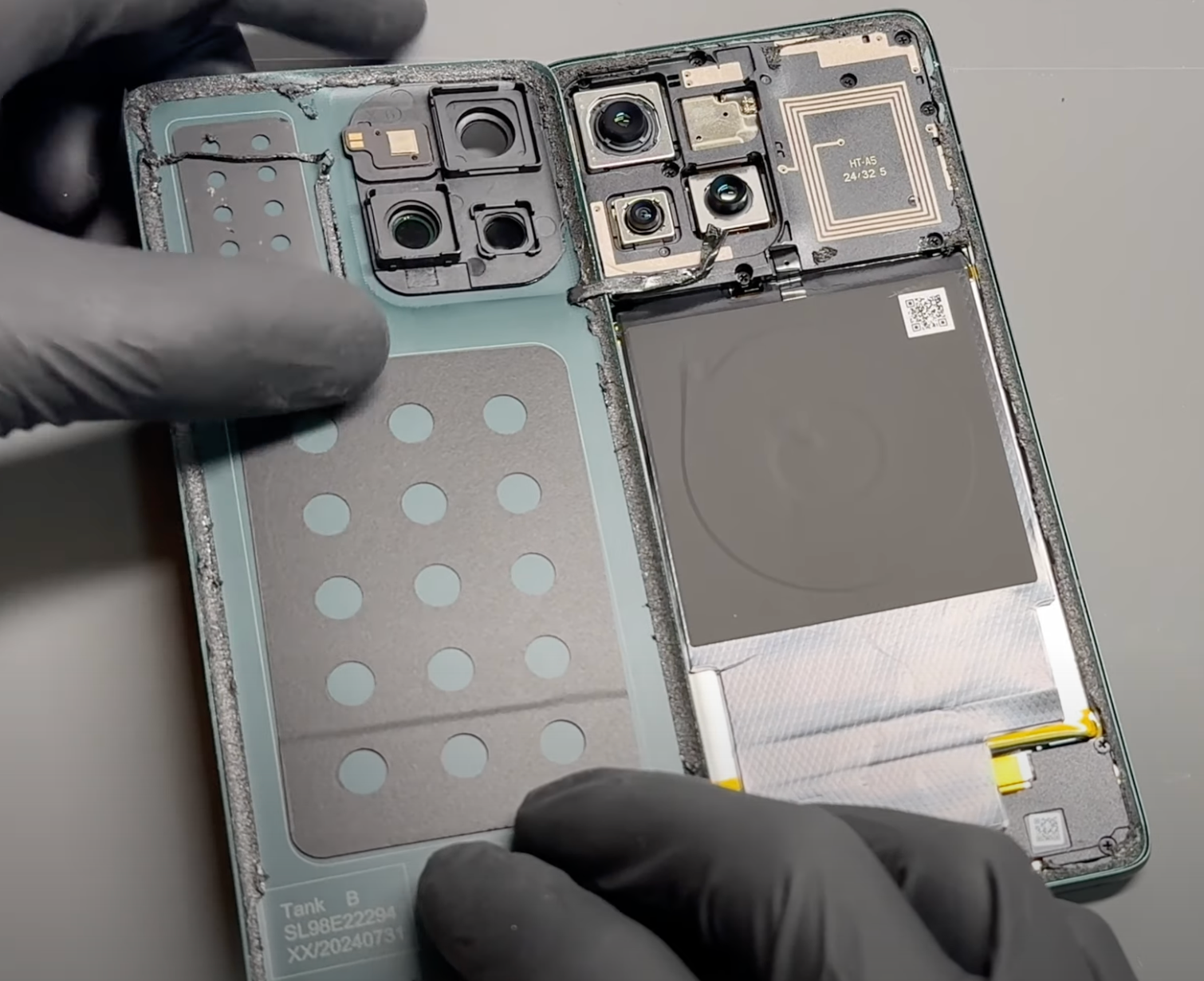
Remove all 10 screws highlighted in the image and place them in a secure area where they are unlikely to be knocked off the table. Keeping them organized will make reassembly easier.
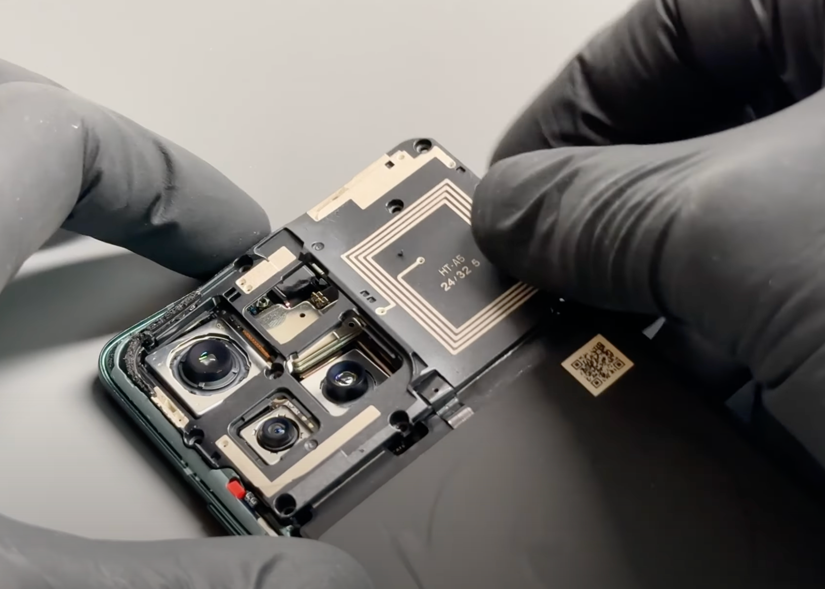
Once the screws are removed, gently pry the adhesive at the bottom of the black wireless charging coil covering the battery. Take your time to avoid tearing or damaging the coil.
Next, release the connector for the sub-board by carefully lifting it from its socket. Then, gently peel up the sticker attached to the sub-board.
Finally, lift out the middle frame, which includes the wireless charging coil, and set it aside in a safe place.
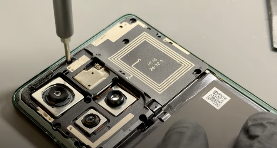
- Remove Camera and Motherboard
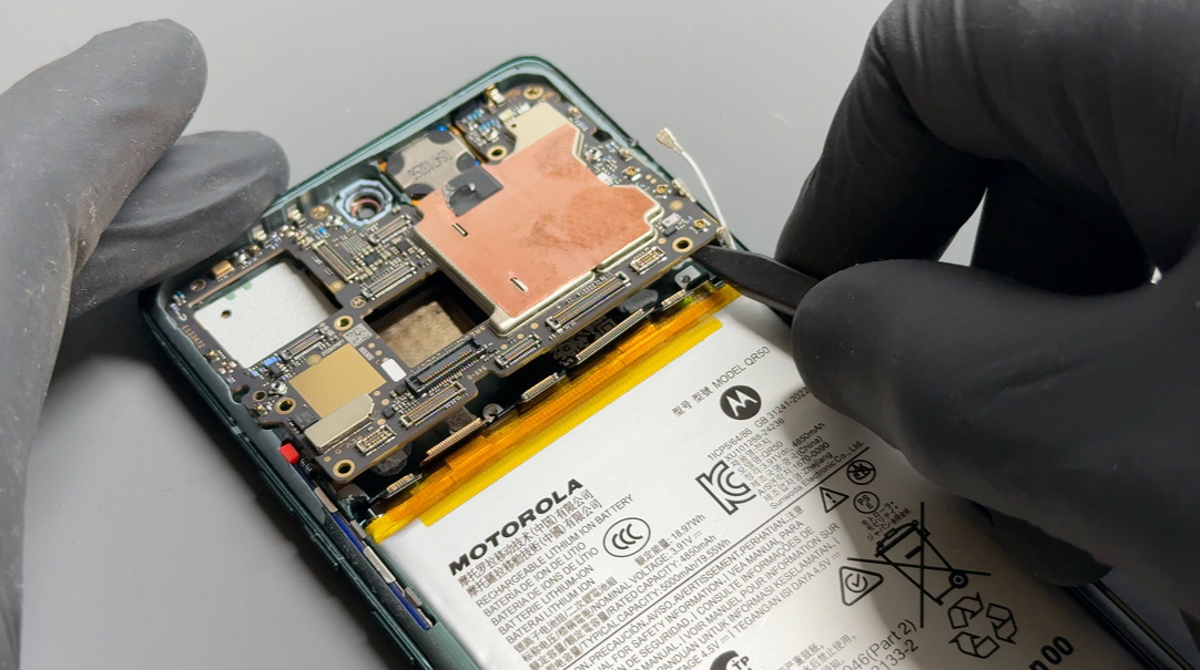
Disconnect the battery connectors on the far left and right. Remove the camera modules by carefully releasing the connectors using a probe tool.
To remove the front camera, gently remove the shielding—be careful not to rip it, as it will need to be reinstalled later. Avoid touching any of the camera lenses directly.
Disconnect the remaining connectors located between the battery connectors that have already been removed. Remove the coaxial connectors by applying slight pressure under the connector neck.
Once all connectors are detached, lift the board out by pulling it directly up from the bottom and towards you.
Using a dry cloth, wipe away any excess residue on both the screen and motherboard.
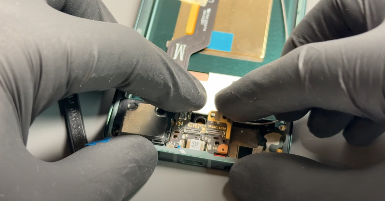
- Charign Port, Motor, Speaker And Antenna Removal
Remove the seven screws holding the bracket and speaker in place. Set aside the silver screw for the speaker, as this is different from the other screws.
Disconnect the two flexible connectors and carefully lift them out of the way. Remove the yellow insulation tape carefully, as it will need to be reused later. Unscrew the silver screw located under the cables that holds a metal bracket in place. Be careful—this screw is different from the others, so keep it separate.
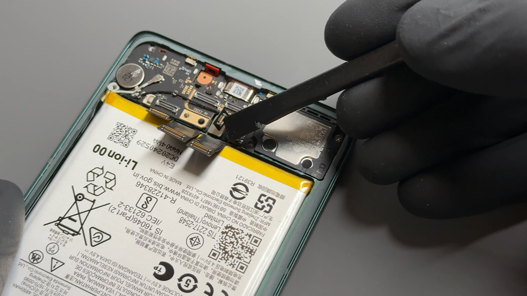
Once the bracket is removed, disconnect the flex cable located next to the battery, followed by the two coaxial cables (black and white) by applying gentle upward pressure under the connectors.
Lift out the daughterboard (the smaller board on the right), which should come out directly. Then, disconnect the last component on the charging port—the optical sensor. Carefully disconnect the connector and lift the module out, avoiding direct contact with the sensor. Using tweezers is ideal.
Apply pressure from the rear of the charging board to pry it up towards you and lift it out.
Next, to remove the loudspeaker, use a plastic probe tool to gently separate the adhesive between the screen’s base and the connection flex cable for the speaker. If needed, apply a little heat to soften the adhesive. Once the cable is separated, the speaker will lift out.
You will notice a small antenna board hidden under where the speaker was. Remove the screw holding it in place and set it aside—this screw must be reused for this part only. Once removed, you can gently pry the board out and disconnect the cable.
Lastly, using the probe tool, separate the vibrating motor from the phone’s frame. Heat may be used if necessary, but in most cases, it will pop out with little effort.
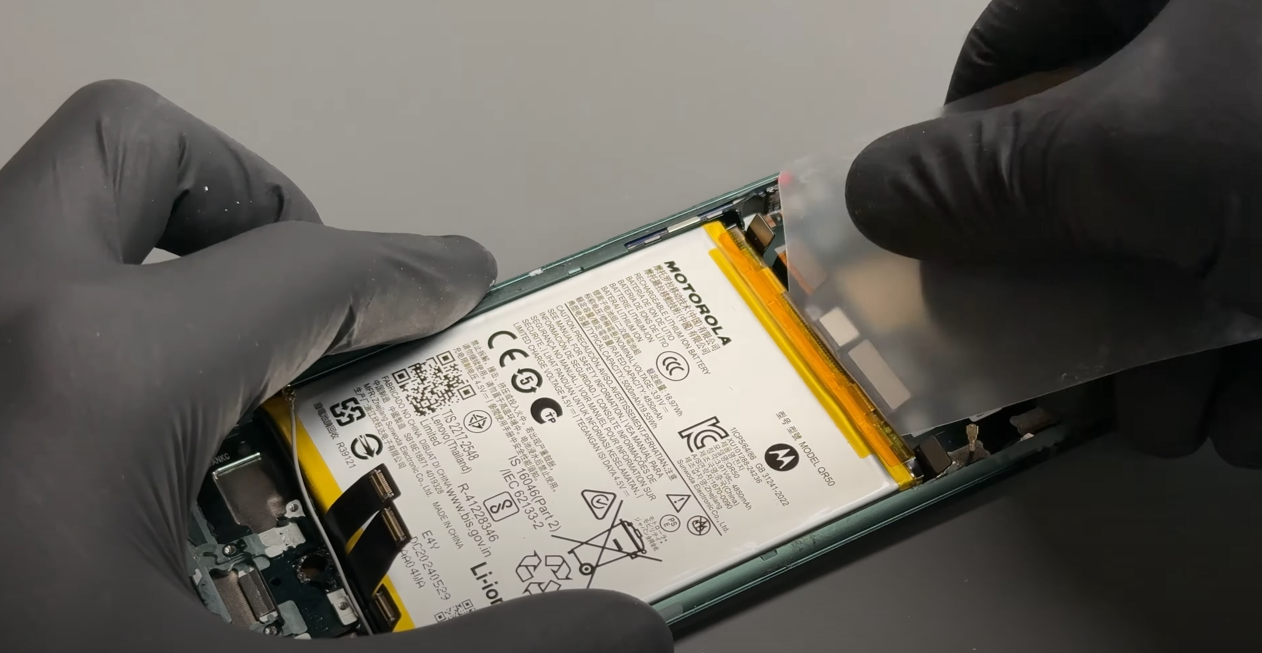
- Battery, Main Flex and Co-Axial Removal
Using a hairdryer on a medium-high setting or a heat gun on a low setting, heat the front of the phone for five minutes until it is warm to the touch.
Using a plastic card tool, position it between the battery and the phone’s frame and slide it around to begin breaking the adhesive bond. This process can take time, and it is crucial not to pull the battery to the point that it starts to warp. It is also vital that no sharp or metal tools are used—no matter how tempting it may be to pry the battery out. The only safe method is to cut through the adhesive.
Reapply heat as needed to keep the phone warm. If necessary, use a suction cup tool on the battery to apply gentle upward pressure while separating the adhesive.
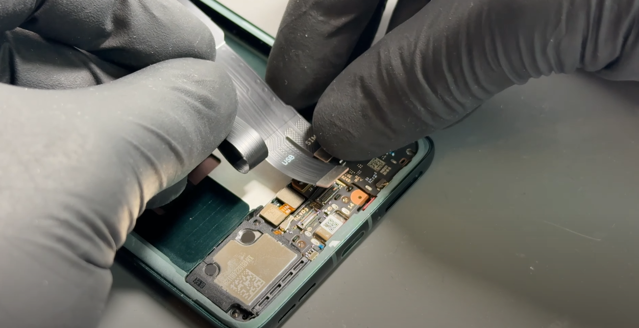
Once the battery is removed, use heat again to warm up the main flex cable. Once heated, pull the cable out slowly but firmly—do not pull from the connector, but instead from the thickest part of the cable. Set it aside once removed.
Lastly, remove the foam gasket covering the two coaxial cables in the frame and set it aside, as it will need to be reused later. Then, remove the coaxial cables.
- New Screen - Motherboard installation
Apply thermal compound to the indicated areas and fit the motherboard from the top of the phone down, hinging it into place so it sits securely in the grooves located in the phone’s frame. Be careful to ensure that all cables are out of the way and do not get trapped under the board.
Reconnect the coaxial cables, making sure to match the correct colors to their positions. From the top down, the order is white, black, then grey.
-
Unpack the new screen and remove any protective films.
Attach the grey coaxial cable to the antenna board and secure it back in place using the same screw that was initially removed. Then, feed the cable into the channel and push it into place as shown in the video.
Reinstall the speaker by pressing it into place and securing the connection flex using the two alignment nipples. Apply pressure on the connector to secure it—the old adhesive should be sufficient to hold it in place.
Next, install the charging port by aligning the USB port with the opening in the new screen’s frame, then pressing it down into place.
Push the vibrating motor back into position—the old adhesive should still be present. If new adhesive is needed, apply it directly to the motor before securing it.
Press the daughterboard into place and install the optical sensor, ensuring you avoid touching the lens. Once installed, softly push the module until it sits securely and flat.
Install the black and then white coaxial cables. You can use your hands or tweezers to align them before applying gentle pressure to click them into place. Once connected, ensure both cables are routed correctly and secured within the brass channel brackets.
Once all cables are in place, remove the adhesive cover on the side of the screen’s chassis. The grey cable should be at the bottom, the black in the middle, and the white at the top—ensure they do not become intertwined.
Press the cables firmly into the chassis so they adhere to the adhesive, then apply the foam gasket.
-
Your old main flex cable should still have adhesive that can be reused. If not, apply new adhesive directly to the main flex cable. Connect the two flex cable connectors to the motherboard, ensuring the cable fits tightly against the board. Run your finger along the flex cable to secure it to the phone’s frame.
Once connected to the motherboard, connect the far right FCP connector to the charge port area then place the metal bracket over the charge port and secure it with the silver screw you set aside earlier—there is no need connect the other two cable at this stage.
Next, apply new adhesive for the battery. Peel off the top layer of the new battery adhesive and apply it directly to the phone’s frame. Remove the top protective layer from the adhesive film and press the battery into place.
Once the battery is installed, connect the two remaining connectors to the charge port assembly. Apply the orange insulation tape and secure the plastic bracket in place using the six black screws.
Lastly, secure the loudspeaker in the bottom right corner using the screw you set aside earlier.
- Middle Frame & Sub-Board installation
Reconnect the sub-board connector and carefully reconnect the FPC (Flexible Printed Circuit), ensuring both are securely seated. The black shielding will remain attached throughout this step.
Once the connections are secure, position the sub-frame with the wireless charging coil back in place, ensuring proper alignment. Apply gentle but firm pressure to the frame to ensure it is fitted correctly and sits flush with the rest of the device.
Finally, reassemble the phone by reinstalling the 10 screws that were removed earlier. These can be fitted in any order—just make sure all screws are tightened securely, but avoid over-tightening to prevent damage.
- Battery Cover Installation
Inspect the phone's frame and battery cover and remove any loose adhesive using tweezers or by gently rubbing it away with your finger to ensure a clean surface.
Align the new adhesive precisely with the edges of the replacement battery cover, then press it firmly into place.
Use your finger to apply even pressure around the adhesive to ensure it bonds securely to the new cover
Carefully remove the protective film covering the top layer of the adhesive, then align and install it onto the phone’s frame. Apply firm, steady, and gentle pressure around the edges of the phone to ensure a secure fit.
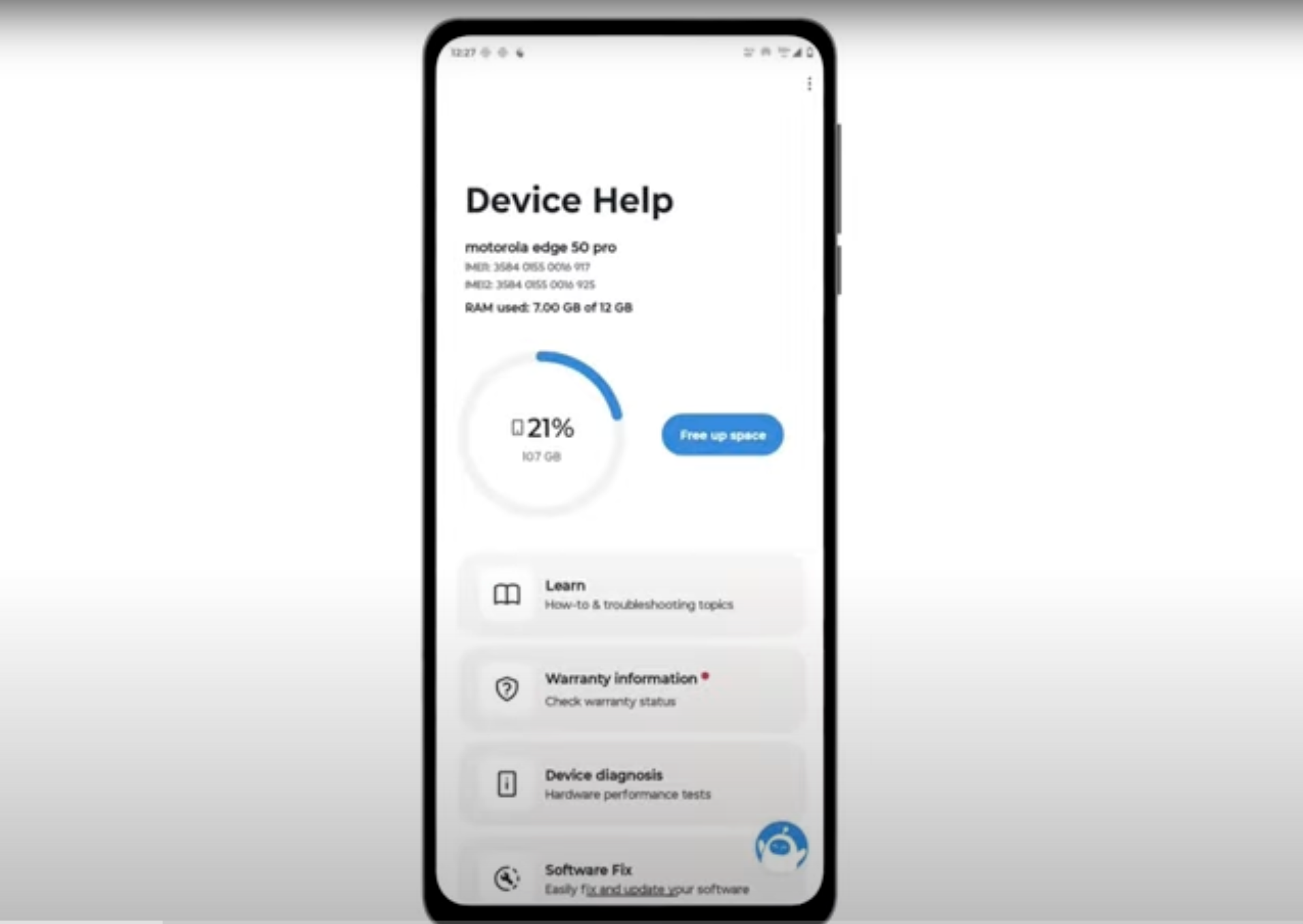
- Final Testing & Device Help App
Download and run Motorola Smart Assist to fully test your device and follow any required configuration.