Hazadous Material Handeling & Disposal
ESD Safety and precautions
Broken Glass Safety

40-45 MINUTES
VIDEO / PHOTO GUIDE
Hazadous Material Handeling & Disposal
ESD Safety and precautions
Broken Glass Safety
This process can take some time, so patience is key. Do not rush the job—batteries can be hazardous, so take your time.
It is best to fully discharge the battery before starting the repair. Never use metal or sharp tools around the battery, never pull or bend the battery, and never apply heat directly to it.
Be careful when reinstalling the motherboard to ensure no cables are snagged or trapped underneath.
Using the SIM card ejection tool, insert it into the release hole and remove the SIM card tray.
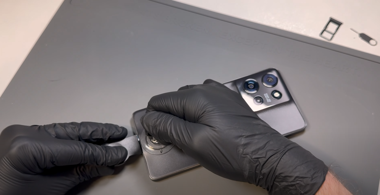
Heat the phone using a hairdryer on a medium setting or a heat gun on a low setting until it is warm to the touch. Once warm, use a plastic blade to create a small gap at the bottom of the phone between the battery cover and the metal frame, using the suction cup if needed. The battery cover is made of a relatively soft material, so don’t worry if it starts to bend slightly—it will return to its normal shape as long as its not bent too much.
Once a gap is made, insert a plastic card and gently slide it around the phone in a back-and-forth motion to begin cutting through the adhesive and breaking the bond. You may need to reapply heat as necessary to keep the adhesive soft.
Be careful not to insert the card too deeply into the phone—1-2 cm should be the maximum depth needed.
Once all adhesive has been cut and the battery cover is loose, wriggle the cover left and right to complete the separation - dont pull it off causing a bend.
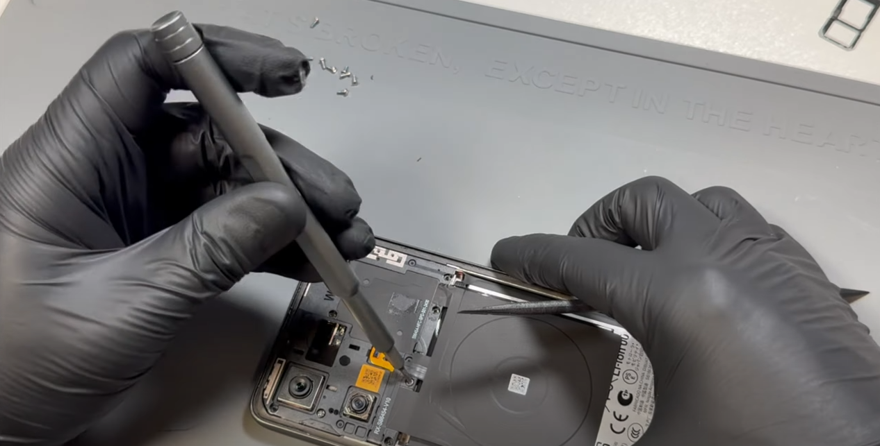
Remove all 10 screws from the subframe. These screws can be tricky to remove, even with a magnetic driver. The best approach is to either use tweezers to lift them out while unscrewing, gently pry them up as they loosen, or leave them in place and remove them after the frame is detached.
Once all screws are removed (or fully loosened but left in place), lift the subframe away from the phone. The wireless charging coil is attached to the black graphene tape with mild adhesive. Carefully separate them by peeling the coil away.
This step can be time-consuming, so it’s important not to rush or be tempted to use prying tools or anything metal. Bending, puncturing, or cutting the battery can be hazardous.
If possible, fully discharge your battery before starting this repair.
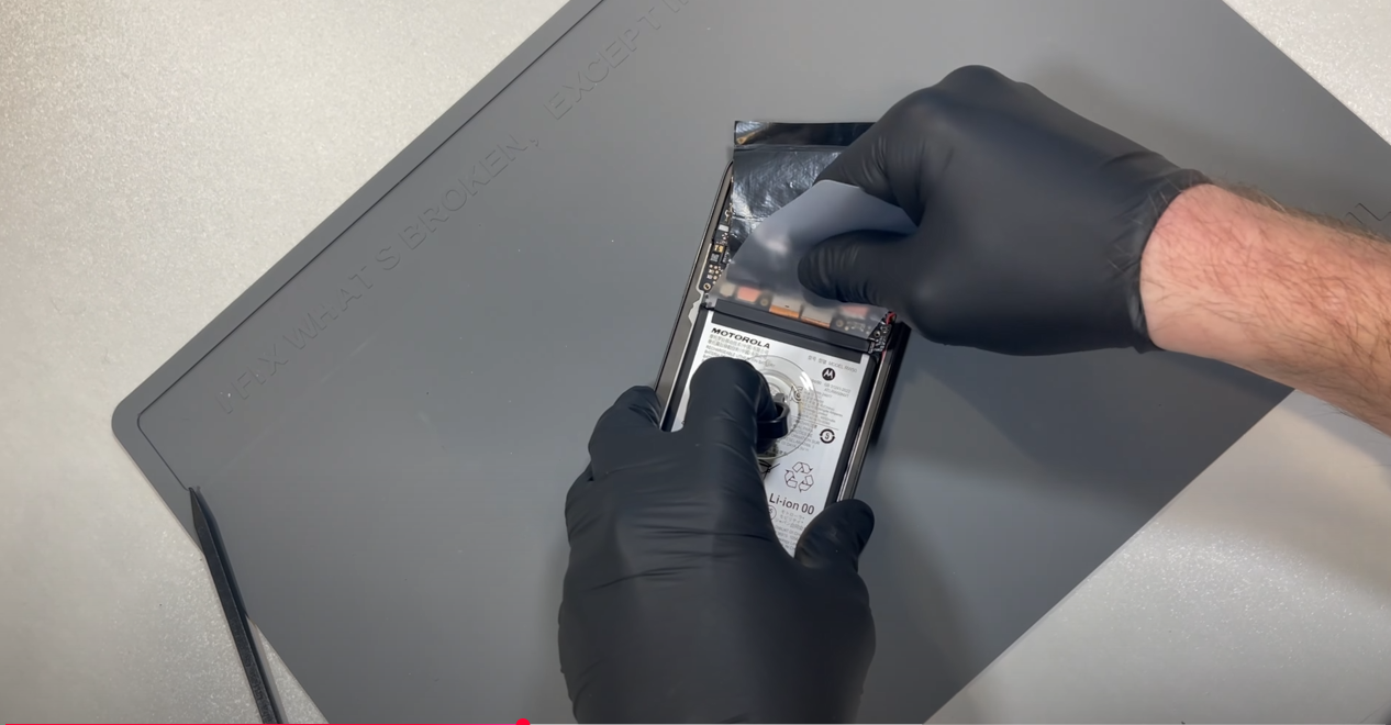
Disconnect the battery connector, flip the phone over, and apply heat using a hairdryer on a medium setting or a heat gun on a low setting. Do not apply direct heat to the battery. This process can take time, as the heat needs to transfer through the screen to the battery adhesive—potentially five minutes or longer. You may need to continue reapplying heat throughout the process.
Using a suction cup to help create upward pressure, slide a removal card along the top edge of the battery. Be mindful of the flex cables located near the battery and avoid snagging them with the tool.
Gradually use a back-and-forth motion to cut through the adhesive bond. Once a few centimeters of adhesive have been cut, reposition the suction cup and focus on the left corner of the battery. Cutting the adhesive in this corner will create a good entry point along the side of the battery.
Continue working along both sides of the battery. Once the adhesive is sufficiently cut, you should be able to remove the battery using the suction cup tool.
Once removed, remove any clumps of old adheisve that remain on the phones frame - leaving the sticky resudue is no problem.
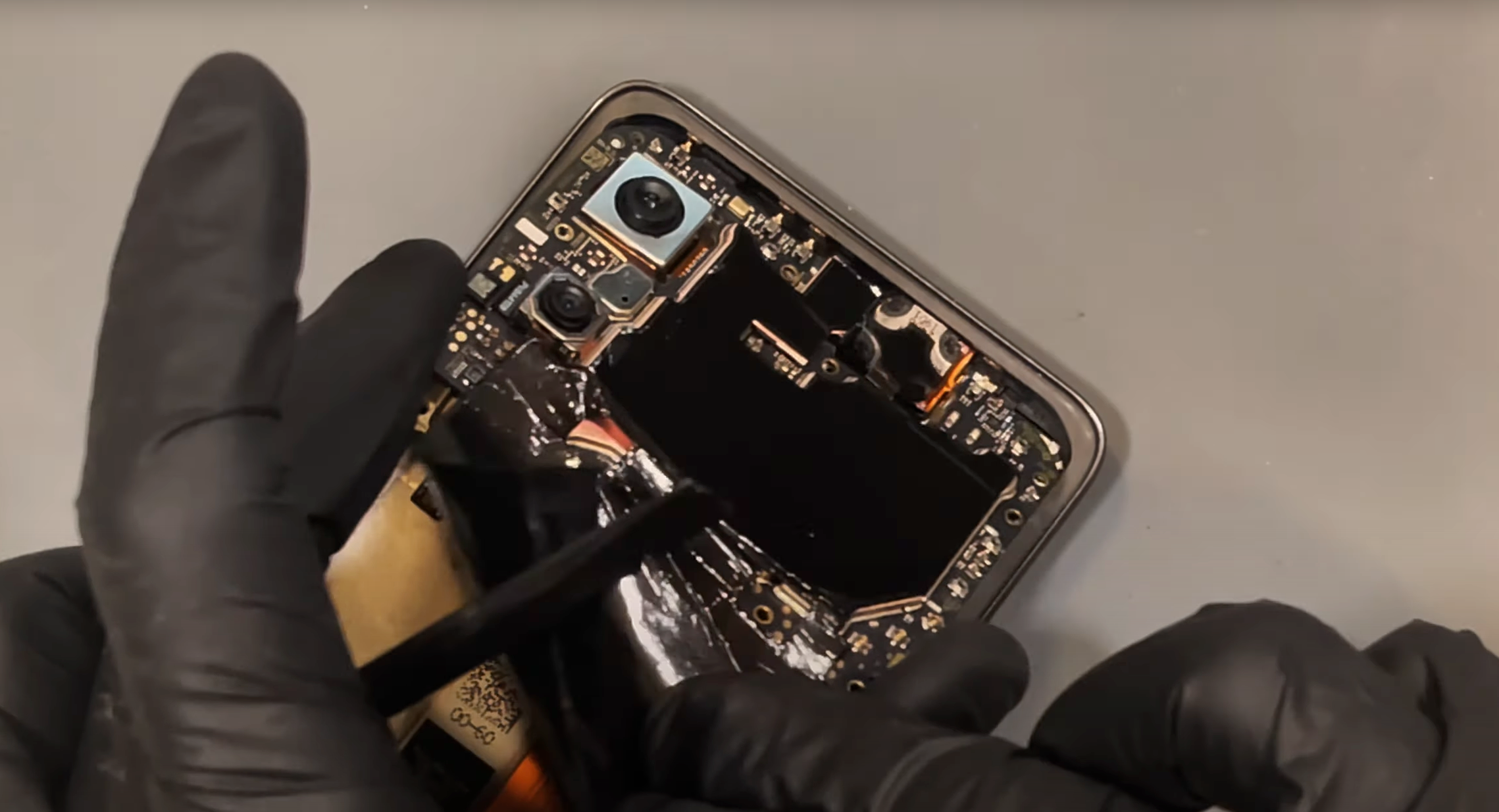
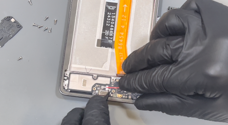
Disconnect the three flex cables at the bottom of the motherboard.
Next, disconnect the coaxial cables, noting their color placement: Red at the top, Black in the middle, and White at the bottom. Use a probe tool under the connector neck and apply gentle upward pressure to release them.
Once all cables are disconnected, use the probe tool at the bottom left of the motherboard to carefully lever it up and pull the board out.
Once removed, clean off the old heat conductive compound from the board.
Remove the seven screws. Once all have been removed, lift out the bracket on the left side.
Disconnect the flex cable from the charge port.
Use a probe tool in the bottom right corner to lift out the loudspeaker. Slowly move the cable out of the way, but leave the speaker connected to the cable for now.
Disconnect the red and black coaxial cables by applying gentle upward pressure from under the neck of the connectors. The red cable is also secured in place with a brass retainer—carefully lift the cable out of the retainer.
Remove the black screw holding the charge port in place and set it aside. You can now remove the charge port.
Return to the loudspeaker and remove the antenna from it. Locate the gap between the board and the bottom of the speaker, then apply slight upward pressure—the board should pop out easily.
To remove the cables from the phone’s frame, use a probe tool to separate the black gasket adhesive securing the cables in place. Set it aside, then remove the cables from the frame.
Lastly, remove the foam gasket adhesive securing the main flex cable. Once removed, carefully lift out the main flex cable. If needed, apply heat to soften the adhesive and make removal easier.

Unpack the new screen.
First, reinstall the old vibrating motor by placing it back into position. The original adhesive should be sufficient for reuse, but if damaged, it can be replaced.
Install the charge port by aligning the USB-C port first, then pressing the board flat into place. Secure it with the black screw you set aside earlier, ensuring it is inserted into the correct hole—the center left screw hole.
Reconnect the antenna board to the loudspeaker by ensuring the white cable is routed through the side channel of the speaker. Position the board under the retaining bracket on the opposite side of the speaker from the white cable, then press down to clip it into place.
Install the loudspeaker, making sure the white cable is correctly channeled in the recess of the speaker as shown in the video. Use a probe tool to push the cable into the bottom of the recess.
Next, connect the red coaxial cable first, then the black coaxial cable. Align the connector to the socket and apply gentle pressure to clip it into place. Do not forget to secure the red cable in the brass retaining bracket.
Use the routing channels provided and push the cables into place as shown in the video, ensuring the black cable sits under the red cable.
Remove the adhesive cover from the center of the new screen—this is for the main flex cable. Once the new adhesive is exposed, connect the main flex cable to the charging port, ensuring it covers the white coaxial cable. Press the flex cable into place on the new screen, then reinstall the foam gasket adhesive to cover the cables. The original adhesive should still be sufficiently sticky.
Double-check that all cables are routed properly into the side channel of the screen. Now, install the bracket back in place and secure it with all screws.
Remove the adhesive cover from inside the side channel of the new screen assembly. Press all cables into the recess, ensuring they are stacked neatly and not twisted or bunched. The correct order is:
Use a probe tool to press the cables into place, then reapply the foam gasket adhesive, which should still be usable from removal.
Fully clean the old adhesive from the phone’s frame. This can be a bit stubborn, so applying heat will help. Use only plastic tools or your finger to rub off the adhesive. If you're installing a new screen, you can skip this step.
Next, fully clean any old adhesive from the battery cover using the same approach as above.
Install the new battery cover gasket/adhesive. Remove the top layer to expose the sticky surface. Take your time aligning the adhesive to the battery cover—gently rest it on top, and if it's not positioned correctly, carefully remove and reapply.
Once satisfied with the placement, apply firm pressure all around the adhesive to ensure it bonds to the battery cover.
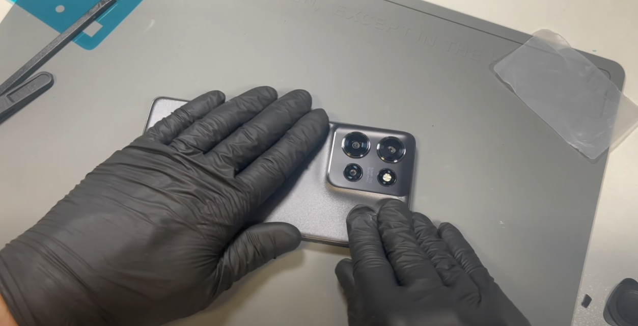
Peel off the protective layer from the adhesive on the battery cover, carefully place the cover onto the phone, and apply pressure all around to ensure a secure fit.
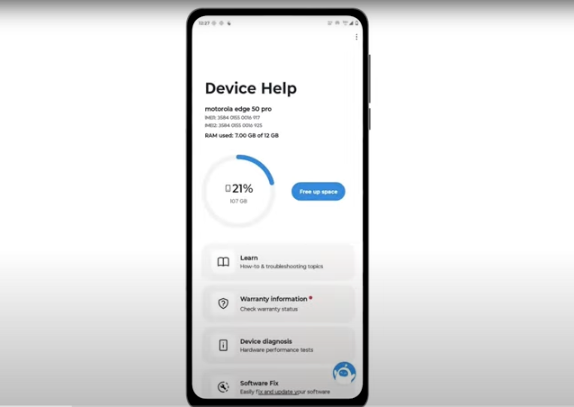
Download and run Motorola Smart Assist to fully test your device and follow any required configuration.