A complete, step-by-step guide to replacing the screen on your Edge 50 Neo—everything you need to safely remove the old display and install the new one with confidence.
Motorola Edge 50 Neo repair

Screen Replacement Edge 50 Neo
50-60 MINUTES
VIDEO / PHOTO GUIDE
Parts Used
Tools & Consumables Required
Technician notes:
This repair does require a bit of focus—especially around the charging port, where the network of cables can be a little tricky to navigate. We recommend taking a few photos as you go to capture the exact cable routing. It'll save you time and help you glide through the guide without second-guessing a thing.
This repair does require a bit of focus—especially around the charging port, where the network of cables can be a little tricky to navigate. We recommend taking a few photos as you go to capture the exact cable routing. It'll save you time and help you glide through the guide without second-guessing a thing.
- Remove SIM Tray, Remove Battery Cover
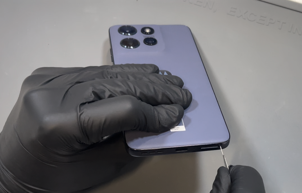

Prepare your work area. Using the SIM eject tool, locate the release hole at the bottom of the phone and remove the SIM tray. Next, use a heat gun on a low setting or a hair dryer on medium to gently heat the back of the phone, focusing on the bottom edge.
Once warmed, use a plastic pry tool or blade to carefully create a gap between the battery cover and the phone frame. When a gap appears, insert the card tool. Continue applying gentle heat as you work the tool around the phone in a counter-clockwise direction, keeping the card inserted no more than 1–2 cm to avoid internal damage.
Once the adhesive seal is loosened, gently wriggle the battery cover to break any remaining adhesive and lift it away from the phone.
- Sub Frame Removal
Using the card tool, gently separate the mild adhesive holding the wireless charging unit in place. Carefully lift and slide it aside while keeping it connected to the phone.
Next, remove the 10 screws from the top section of the frame. Use tweezers if needed to help lift them out. Once all screws are removed, use a plastic probe tool in the bottom-right corner of the frame to detach and lift it away. Set the frame aside.
With the shielding exposed, lift it up and disconnect the two outermost connectors—these are for the battery and must be removed before continuing with the repair.
- Old Screen Component Removal
Before installing the new screen, all components from your old screen must be removed.
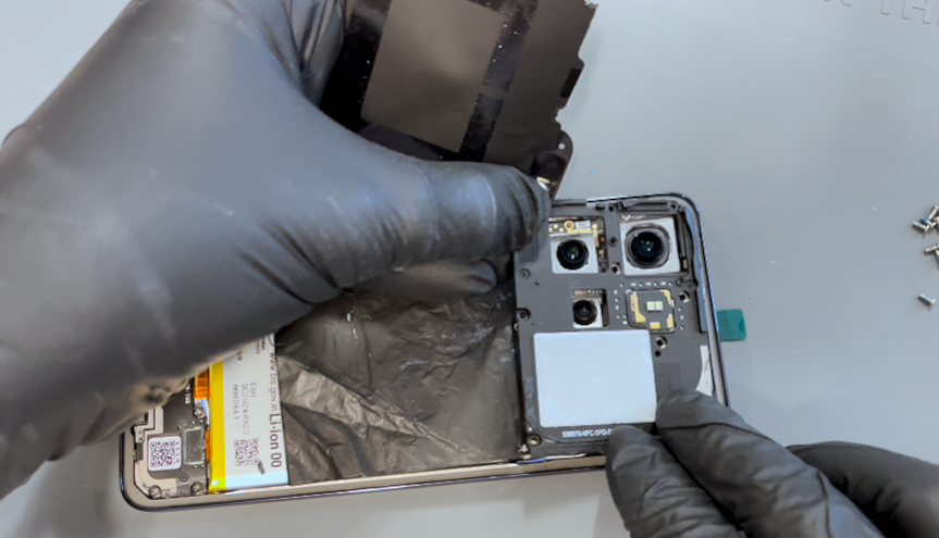
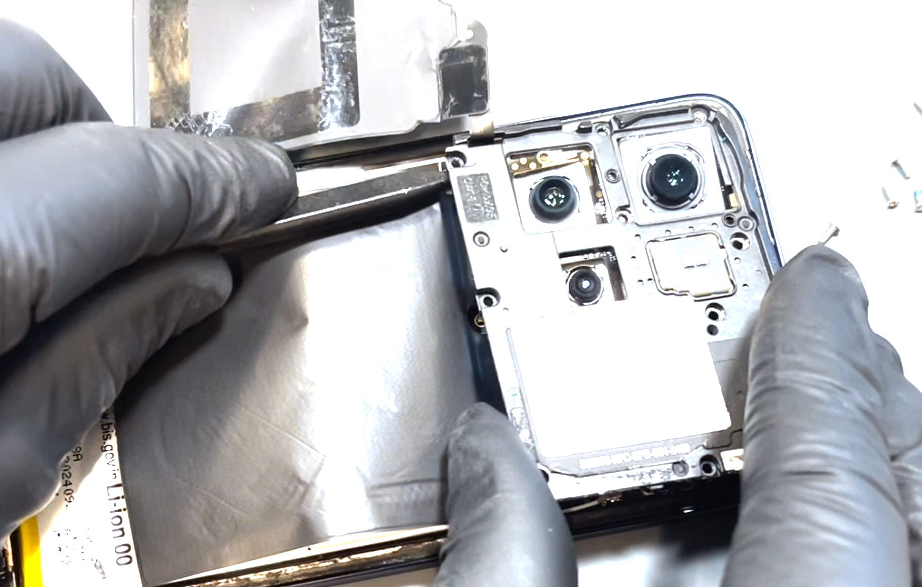
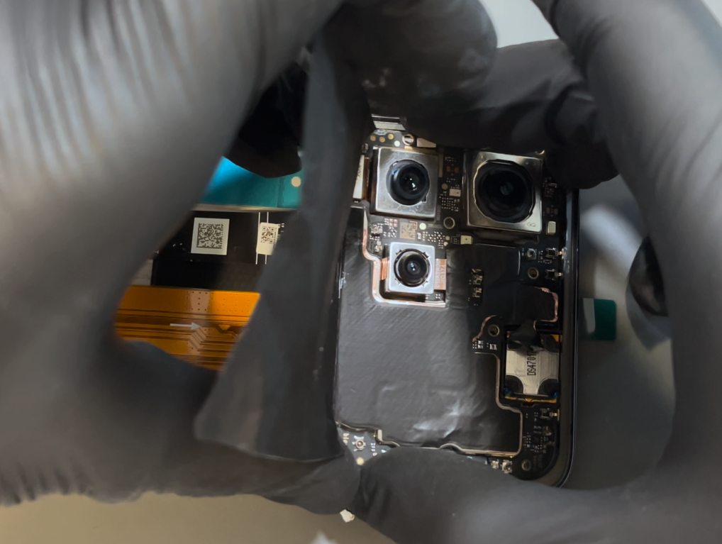
Start by carefully peeling back the black and copper shielding using a plastic probe tool. These layers are fragile, so take your time. Once exposed, remove the front-facing camera.
For the remaining two cameras, we recommend removing the motherboard. Disconnect the two coaxial cables using a probe tool under the metal necks of the connectors. Then, disconnect the remaining two flex cables on the motherboard.
Use the probe tool to gently pry up from the bottom-right corner of the motherboard and lift it out. Clean off any remaining thermal paste and set the board aside.
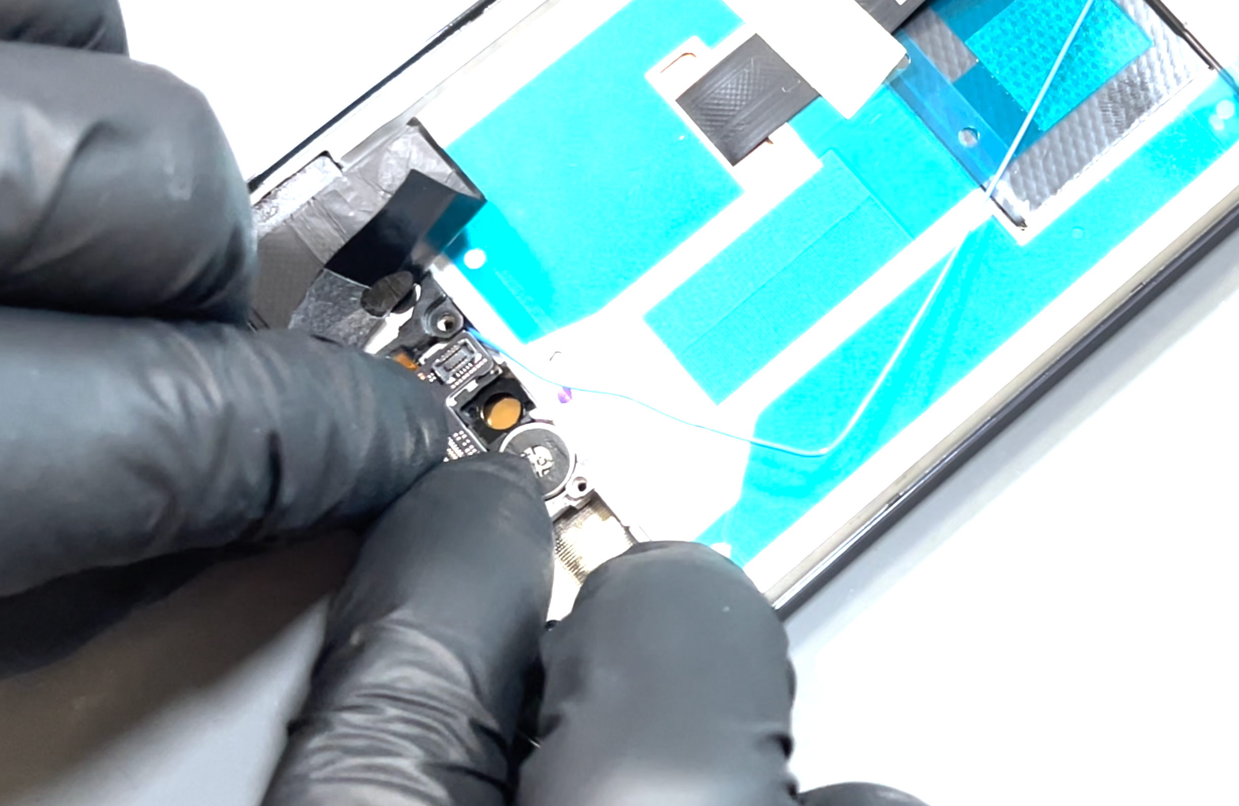
Next, gently peel back the shielding film on the loudspeaker to free it from the bracket. Remove the five screws holding the charging port bracket and lift it away. Disconnect the flex cable on the daughterboard, as well as the black coaxial cable—note the retaining clip here. Then disconnect the main flex connector and the white coaxial cable.
Remove the screw securing the metal retaining bracket and lift the bracket out with tweezers. Disconnect the optical sensor cable that was beneath the bracket. Remove the final screw from the loudspeaker.
The daughterboard is not fixed with adhesive and can be gently pried up from the rear. Locate the small opening on the right side of the charging port and use a probe tool to lift the charging assembly out. Remove the optical sensor next, using the probe tool to lift it gently.
Using the pointed end of the probe tool, separate the loudspeaker cable from the chassis—this is held with mild adhesive. Once free, remove the loudspeaker and set it aside.
Beneath the speaker is a small antenna board. Remove its screw and lift the board out; you can leave the blue coaxial cable attached. Use metal tweezers to lift out the vibration motor—it should come away easily with its adhesive intact.
The antenna cables are secured to the side and bottom of the phone’s frame. Remove the protective foam strips and set them aside for reuse later. Once the cables are free, remove them completely from the chassis.
Lastly, remove the main flex cable, which is also held in place with mild adhesive. Pull gently but firmly until it releases from the frame.
- New Screen - Installing Charing Assembly
Remove your new screen from the packaging. Using tweezers, carefully remove the protective film covering the hole for the optical sensor and the adhesive strip for the loudspeaker connector.
Begin by installing the antenna board and securing it with the screw. Refit the loudspeaker—this will drop neatly into place. Use the probe tool to align the connector, which has two retaining nipples to ensure proper positioning. Press the vibration motor back into its slot.
Next, install the charging port by aligning the USB-C connector with the cutout in the phone’s chassis. Press it into place, ensuring the antenna cable isn't snagged or trapped underneath.
Install the optional sensor by pressing it into place and reconnecting its flex cable.
Before fitting the metal bracket, install the daughterboard—it will rest in position but won’t be fully secured yet. Remove the protective blue film from the centre of the new screen to reveal the adhesive for the main flex cable. Align the main flex using the guide marks on the screen and press it down to secure.
Now install the metal bracket, ensuring the blue coaxial cable is routed above the bracket. Secure the bracket with its screw.
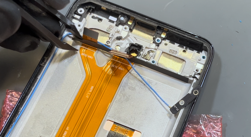
Reconnect the white coaxial cable by aligning it and pressing gently until it clicks into place. Route it over and around the same path as the blue cable, as shown in the video. Once routed, reconnect the flex cable that holds them in place.
Use the channel in the phone’s frame and a probe tool to press the blue and then white coaxial cables neatly into the recess. Reconnect the flex cable that runs over them.
Reconnect the black coaxial cable, making sure it clips into the retaining bracket on the daughterboard.
Refit the main port bracket, then secure it with the five screws and the single screw in the round speaker.
Reapply the foam buffer strip over the bottom connectors on the main flex cable. Press it into place—it may feel slightly loose, which is fine, as it's designed to cushion the battery and will be secured once the battery is installed.
Remove the protective film from the cable channel on the right side of the phone’s frame. Neatly arrange the cables at the base of the chassis without twisting them. Run your finger over the cables to press them into place.
Finally, reapply the protective strip and use a tool to press it down firmly so it bonds securely.
- Motherboard & Battery Installation
Apply new thermal paste to the indicated areas on the phone’s screen. The motherboard will slot back into the recess at the top of the chassis—carefully hinge it in, making sure no cables are trapped beneath it. Once the board is correctly seated and all cables are clear, gently press the shielding back onto the earpiece speaker.
Reconnect the two flex cables and all three coaxial cables—the color of each is labeled on the board. Use tweezers to align each coaxial connector, then apply light pressure until it clicks into place.
Finally, install the battery. Remove the protective adhesive film and fit the battery from the bottom, making sure it sits snugly against the foam buffer installed earlier. Once in position, apply even pressure across the battery to ensure it bonds securely to the screen.
- Sub Frame Install
Reconnect the battery terminals (the far left and right flex cables), then rest the sub-frame in place. Apply even pressure around the edges—you’ll hear it snap securely into position.
Once the frame is seated, reinstall all screws to secure it. Finally, position the wireless charging coil back in place, making sure the alignment nipple on the frame fits into the corresponding hole in the flex cable for proper positioning.
- Battery Cover Installation
Ensure the phone’s frame is clean and free from adhesive. If you've just replaced the screen, there's no need to clean the chassis. Light adhesive residue on the frame is acceptable, as long as there are no thick clumps you can feel with your finger. If you're reusing your old battery cover, make sure all old adhesive is completely removed before applying the new adhesive. Once both surfaces are clean, peel the protective film from the battery cover adhesive to expose the sticky side. Loosely align the adhesive with the top edge and corners of the battery cover, resting it in place until you’re satisfied with the positioning. When aligned correctly, press along the adhesive with your fingers to help it bond, then allow it to rest for 5 minutes. After resting, carefully peel off the blue protective film to expose the adhesive—be sure not to accidentally lift the adhesive itself. If you’re installing a brand-new battery cover, remove the protective film from the inside of the camera lenses as well. Finally, press the battery cover into place and apply firm, even pressure around the entire edge of the phone until it feels securely sealed.
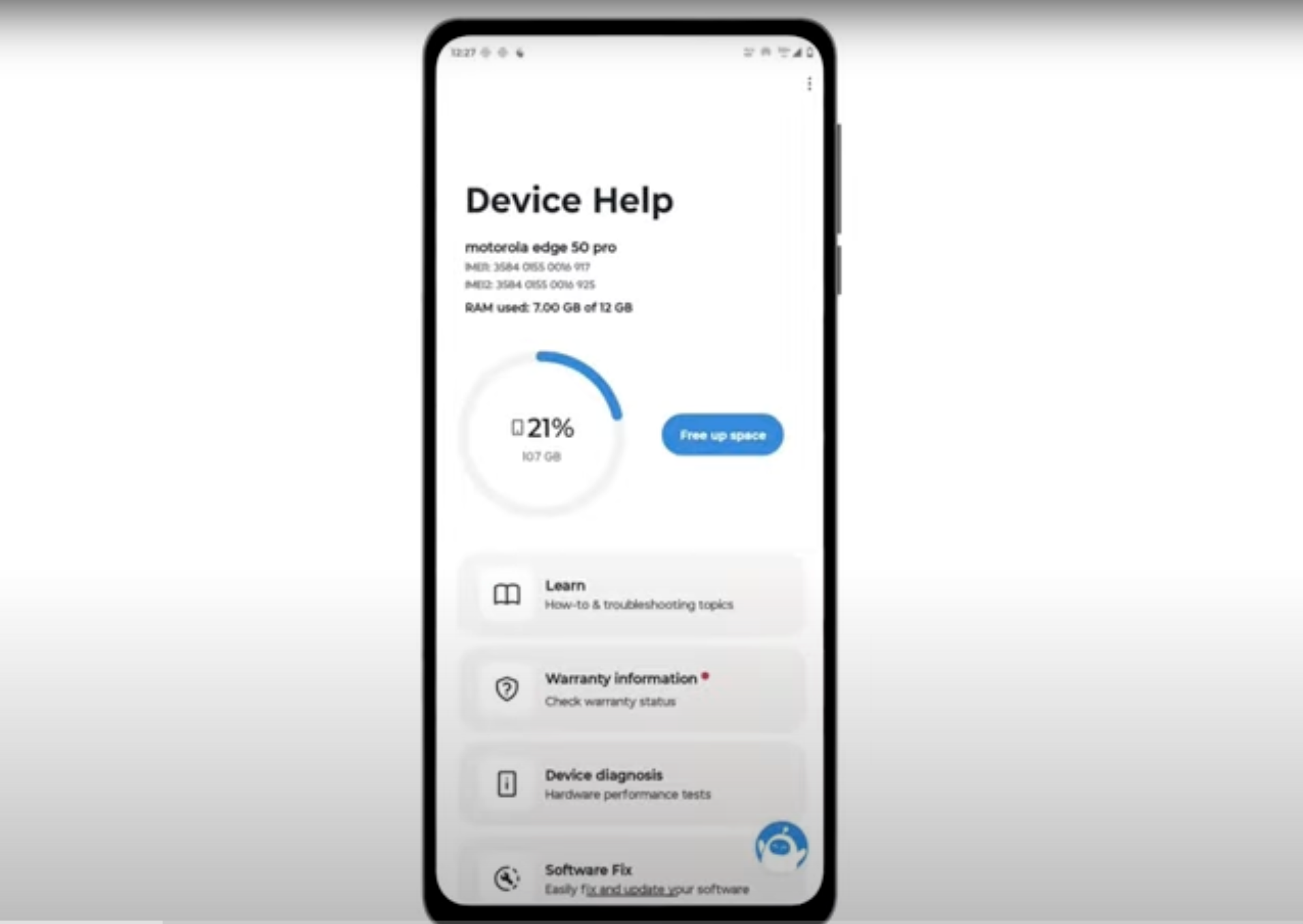
- Final Testing & Device Help App
Download and run Motorola Smart Assist to fully test your device and follow any required configuration.